Photo Gallery

GE Genura in details

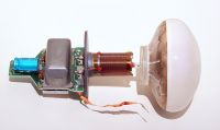
This shot presents an exploded view of a GE Genura induction fluorescent lamp, showing the electronic driver on the left, the antenna, and the discharge vessel on the right. The lamp operates at 2.5 MHz and was the first commercial self-ballasted energy-saving lamp of its kind. The RF oscillator is inside a Faraday cage (the grey box next to the blue capacitor) and the discharge vessel is provided with a galvanic shield made of silver. The latter facilitates the discharge ignition and reduces the lamp's EMI emission.


Keywords: Lamps

GE Genura in details


This shot presents an exploded view of a GE Genura induction fluorescent lamp, showing the electronic driver on the left, the antenna, and the discharge vessel on the right. The lamp operates at 2.5 MHz and was the first commercial self-ballasted energy-saving lamp of its kind. The RF oscillator is inside a Faraday cage (the grey box next to the blue capacitor) and the discharge vessel is provided with a galvanic shield made of silver. The latter facilitates the discharge ignition and reduces the lamp's EMI emission.

Genura_exploded_view.jpg DSCF0197m.jpg CC_Air_m.jpg CC_Water_m.jpg Philips_126564.jpg
File information
Filename:Genura_exploded_view.jpg
Album name:Max / Misc lamps and lighting
Keywords:Lamps
Filesize:715 KiB
Date added:12 Jul 2026
Dimensions:1800 x 1073 pixels
Displayed:94 times
DateTime Original:2004:01:01 01:04:10
Exposure Time:1/15 sec
FNumber:f/5.6
Flash:No Flash
Focal length:41 mm
ISO:400
Model:Canon EOS 350D DIGITAL
Software:Adobe Photoshop 25.7 (Windows)
White Balance:1
URL:https://trad-lighting.net/gallery/displayimage.php?pid=1378
Favourites:Add to Favourites

Comment 1 to 5 of 5
Page: 1

Tuopeek   [Sun 12 Jul 2026 at 18:00]
It goes to show a lot of the build costs in these lamps relates to the quality of RF shielding required in the construction to pass EMC rules.
Max   [Mon 13 Jul 2026 at 06:34]
Indeed. Also, what I did not mention is that the bulb is internally coated with a conductive layer of fluorine-doped tin oxide. It is "grounded" (in the RF sense of the term) via its strong capacitive coupling to the back shield (i.e., the silver coating). The EMI shielding is quite extensive in this one and that's a direct consequence of the use of a simple open-ended magnetic antenna.

Here's another interesting detail. Notice the radial cuts in the external shield of the bulb? Any idea why GE implemented such pattern? Very Happy
Ria   [Mon 13 Jul 2026 at 12:28]
Exploded..? That doesn't sound very good Mind Blown Mr. Green

We've got one of those somewhere, think it came from you Max, thanks a lot Bulb Man
Tuopeek   [Mon 13 Jul 2026 at 14:42]
@Ria: Engineers just love exploded diagrams. I rebuilt a car with just exploded diagrams Smile

@Max: My first guess to the radial pattern would be to reduce inductive coupling on the coating. Given you really want all the energy in the plasma. Reminds me of why Tesla Coils don't use a continuous loop 'strike guard rails' around primary coils.
Max   [Tue 14 Jul 2026 at 18:43]
That's correct! That radial pattern in the silver coating is to limit the intensity of the current induced by the alternating magnetic field - current which would generate a magnetic field in (phase) opposition to that produced by the antenna, hence potentially reducing the electromotive force available to the plasma. So, this pattern is there to prevent any significant degradation of the power coupling to the plasma.

Comment 1 to 5 of 5
Page: 1